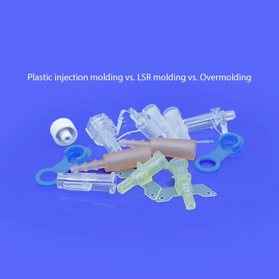
Plastic vs. LSR Injection Molding vs. Overmolding
Introduction
Choosing between plastic injection molding, LSR (liquid silicone rubber) injection molding, and overmolding is rarely about “which process is best.” It’s about which process can hit your functional requirements, cosmetics, compliance obligations, and total cost targets with predictable yield.
This guide compares the three across four practical dimensions: how each process works, how materials affect design, what quality/compliance risks to plan for, and what actually drives cost.
It’s written for engineers, product designers, and sourcing managers who need a clear selection framework. If you’re skimming, read the H2s. If you’re making decisions, the H3s go deeper on design rules, validation, and cost drivers.
How each process works
This section gives a concise process-level view so you can map requirements (geometry, surface finish, compliance, and volume) to the most realistic manufacturing route.
Plastic injection molding in brief
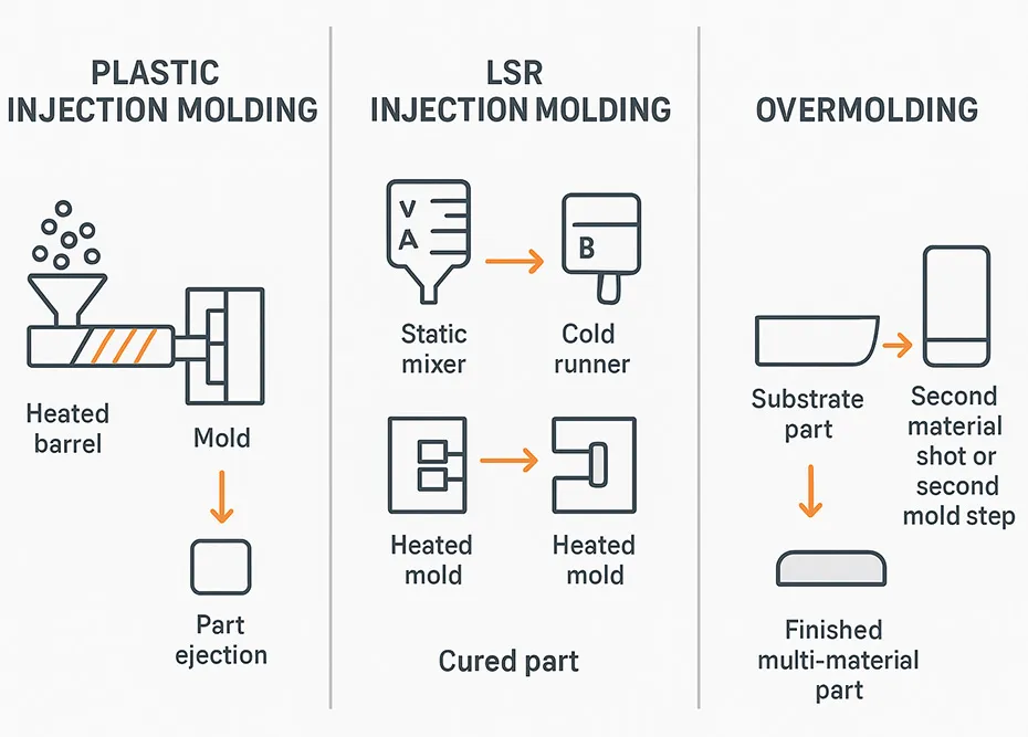
Plastic injection molding forms parts by melting thermoplastic pellets, injecting the melt into a cooled mold, and solidifying the part through cooling. The cycle is dominated by fill/pack and cooling time, plus part ejection.
What matters for downstream performance:
-
Melt flow and packing determine sink risk, dimensional stability, and knit line strength.
-
Cooling uniformity drives warpage and cycle time.
-
Gate location and venting influence cosmetics and trapped air (burn marks, short shots).
Plastic injection molding is typically the most mature option for high-volume, rigid parts with tight repeatability requirements—assuming the geometry and resin can be processed without excessive stress or cosmetic defects.
LSR injection molding in brief
LSR injection molding dispenses two liquid components (A/B), meters and mixes them, and injects the mixture into a heated mold where it cures. Unlike thermoplastics (which cool to solidify), LSR parts solidify by crosslinking.
Two process traits drive most design and quality decisions:
-
Low viscosity before cure means LSR will flow into fine features—but it also finds every gap, so parting line control and venting strategy are critical.
-
Cure kinetics (time/temperature) set cycle time and influence post-cure needs for certain applications.
LSR is often chosen when you need elasticity, a wide operating temperature window, sealing performance, or biocompatibility/cleanliness controls that are hard to maintain with other elastomer processes.
Overmolding (two-step vs two-shot)
Overmolding creates a multi-material part by molding one material (the substrate) and molding a second material over it (the overmold). It’s used to combine functions—like a rigid structure with a soft seal or grip—without separate assembly.
There are two common routes:
-
Two-step overmolding: mold the substrate first, then transfer it to a second tool or second operation for the overmold. This reduces tooling complexity but adds handling, alignment risk, and potential contamination between steps.
-
Two-shot (2K) overmolding: mold both materials in one machine cycle (often with a rotating platen/indexing tool). This improves repeatability and throughput at volume, but increases tool and process complexity.
In both cases, the core engineering question is the same: Will the interface hold up in real use (mechanically, thermally, chemically), and can you validate it consistently?
Materials and design impacts
The material category (thermoplastic vs LSR vs multi-material stack) determines how the part fills, where defects originate, and which DFM rules are non-negotiable.
Thermoplastics: behavior and design rules
Thermoplastics are stiff enough to serve as structural components, but they carry design implications that show up as shrink, warp, sink, and cosmetic variation.
Key design rules to keep front-of-mind:
-
Wall thickness discipline: large thickness transitions invite sink, voids, and warpage. When you need stiffness, ribs are usually a safer path than thick walls.
-
Draft and ejection strategy: draft angles, texture allowances, and ejector placement should be decided early—especially for cosmetic faces.
-
Gate placement and flow length: gate location affects weld lines and fiber orientation (for filled resins), which can change strength and appearance.
If your part is dimension-driven, treat resin choice, gate strategy, and cooling layout as a single system—not separate decisions.
LSR: behavior, venting, and flash control
LSR behaves like a liquid during fill and then transitions to a solid elastomer during cure. That creates unique DFM priorities:
-
Venting is not optional: air must leave the cavity as LSR fills. Poor venting increases short shots, trapped air, and cosmetic defects.
-
Flash control is a tooling + process problem: because uncured LSR is low viscosity, even small parting line gaps can create flash. Mold fit, clamp force, parting line design, and injection parameters must work together.
-
Parting line and shutoff design drive yield: shutoffs need enough land area and hardness strategy to resist wear without causing damage or sticking.
Pro Tip: For LSR, design reviews that focus only on the part model often miss the real yield drivers. Ask to review parting line intent, vent locations, and shutoff strategy early—before steel is cut.
Overmolding: compatibility and interlocks
Overmolding success depends on what actually holds the two materials together. There are two broad attachment mechanisms:
-
Chemical/thermal adhesion: the overmold bonds to the substrate at the interface. This is strongly material-dependent and sensitive to surface chemistry, mold temperature, and time between steps.
-
Mechanical retention: features like undercuts, holes, grooves, and “dovetail” shapes lock the overmold in place regardless of chemical compatibility.
Design implications:
-
If you can’t guarantee adhesion (or it will be exposed to harsh fluids/heat cycling), design mechanical interlocks so the joint isn’t relying on chemistry alone.
-
Substrate geometry needs to control overmold flow front so you avoid knit lines right at the functional sealing area.
-
Handling between steps (for two-step) can introduce release agents, skin oils, or dust—all of which can reduce bond strength.
Quality, testing, and compliance
For regulated OEM programs, “quality” includes dimensional performance, defect containment, documented validation, and traceability—not just visual inspection.
Tolerances, shrinkage, and cosmetics
All three processes can produce repeatable parts—but they fail in different ways.
-
Plastic injection molding: shrinkage and warpage are dominated by resin behavior, packing, and cooling uniformity. Cosmetic issues often trace back to gate blush, weld lines, sink, and burn marks.
-
LSR injection molding: dimensional variation often links to cure state, parting line wear, and demolding distortion. Cosmetic issues frequently involve flash, trapped air, and surface blemishes from venting strategy.
-
Overmolding: tolerances are two problems at once—substrate variation plus overmold variation—and they interact at the interface. Misalignment and inconsistent wall thickness at the overmold can create cosmetic step lines or functional leakage paths.
A practical way to avoid surprises is to define which dimensions are critical and then align the process controls and inspection plan to those CTQs (critical-to-quality characteristics).
Adhesion validation for overmolds
“Adhesion looks good” isn’t a validation plan. Overmolds need test methods that reflect how the product will actually be loaded.
Common validation approaches include:
-
Peel-style tests for interfaces that will be “unzipped” or lifted in use
-
Shear/tensile-style tests for interfaces loaded in compression or sliding
-
Environmental conditioning (heat aging, thermal cycling, chemical exposure, humidity) to expose failure modes that don’t show up right after molding
Acceptance criteria should be defined in terms of:
-
Minimum force (where measurable)
-
Failure mode (cohesive tear within the elastomer vs adhesive separation at the interface)
-
Post-conditioning performance (does the joint survive after the worst-case environment?)
If your program is regulated or safety-critical, document the test fixtures, sample size rationale, and traceability from test samples back to material lots and process conditions.
Medical-grade LSR and cleanrooms
When LSR is used in medical or contamination-sensitive applications, the process choice becomes a quality system decision—not just a manufacturing decision.
Key topics to clarify with any supplier:
-
Quality management system alignment: For medical programs, an ISO 13485 quality system is commonly used to control document change, training, inspection records, and traceability.
-
Controlled manufacturing environment: Cleanroom class, gowning practices, cleaning validation (where applicable), and material/part handling flows matter—especially for parts that contact fluids, drugs, or patient tissue.
-
Material traceability and lot control: Define how the supplier tracks incoming material lots, mixed batches, and finished goods lots, and how that links to inspection and release records.
-
Tooling and process controls that target flash and contamination: LSR parts can be sensitive to particulate and to flash that may migrate or shed. Tooling maintenance plans and shutoff wear monitoring should be part of the control strategy.
As a practical example of what to look for, JESilicone states capabilities that include LSR tooling/mold-making, LSR injection molding, and an ISO 13485-certified manufacturing setup with a 100,000-class clean workshop for medical-grade production. In a supplier evaluation, those statements should translate into auditable artifacts—such as cleanroom procedures, training records, equipment maintenance logs, and traceability documentation tied to your specific part and material.
Applications and when to choose
Use these patterns as a first-pass filter, then confirm with DFM feedback and a validation plan matched to your risk level.
Where plastics excel
Plastic injection molding is usually the first choice when:
-
The part is primarily structural (housings, brackets, carriers)
-
You need high throughput with low per-part cost at volume
-
The design can tolerate thermoplastic realities (draft, weld lines, sink management)
-
You need insert molding of metal components or threads without adding a second material layer
If you can keep the design mold-friendly (uniform walls, smart gating, predictable ejection), plastics tend to win on cost and supply chain maturity.
Where LSR shines
LSR injection molding tends to be the best fit when you need:
-
Elastic sealing with consistent compression set behavior
-
Complex soft geometries (thin membranes, valves, intricate sealing lips)
-
Temperature and environmental resilience that is hard to get from many thermoplastic elastomers
-
Cleanliness and traceability controls that align with regulated production workflows
LSR also becomes attractive when you want to eliminate secondary operations (like trimming or assembly) and can design the tool to control flash and venting.
When overmolding wins
Overmolding is usually worth the complexity when it removes a real downstream problem:
-
You’re replacing a multi-part assembly (gasket + housing + adhesive) with a single integrated part
-
You need positional accuracy between rigid and soft features (a seal molded exactly where it needs to be)
-
You want to eliminate adhesive variability or operator-driven assembly steps
Two-step is often a pragmatic ramp strategy; two-shot (2K) often makes sense when volume, automation, and repeatability justify the tool investment.
Cost drivers and ROI
Cost is usually a stack of trade-offs: tooling amortization, machine time, labor/handling, scrap, and the cost of defects that escape. Overmolding economics, in particular, often hinge on whether you can eliminate assembly steps and stabilize yield.
Tooling and cavitation
Tooling cost isn’t just “one mold vs another.” It’s driven by complexity that affects build time, qualification effort, and long-term maintenance.
Typical tooling cost drivers by process:
-
Plastic injection molding: high cavitation, hot runner choices, cooling layout complexity, slides/lifters for undercuts.
-
LSR injection molding: precision parting line/shutoffs for flash control, venting strategy, cold runner systems, demolding strategy for soft parts.
-
Overmolding: two materials often mean more tooling stations, more alignment requirements, and (for 2K) an indexing mechanism and tighter process window across both shots.
Cavitation decisions should be made alongside quality targets. Higher cavitation can improve economics, but it can also tighten the window for balancing fill, temperature control, and consistent demold.
Cycle time and automation
Cycle time is the biggest lever on piece price after material cost, but it behaves differently across processes:
-
Thermoplastics are often cooling-limited; automation is mature (pick-and-place, degating, in-line inspection).
-
LSR is cure-limited; automation is common but must account for part flexibility and potential tackiness at demold.
-
Overmolding can be handling-limited in two-step (transfer and fixturing), while 2K can be highly automated but needs more robust process monitoring.
If your program is sensitive to labor variability, overmolding often pays back when it removes touch labor and reduces rework—even if tooling is higher.
Material, scrap, and volume break-even
A clean break-even analysis should separate three cost buckets:
-
Fixed cost: tooling, qualification, any special fixturing
-
Variable processing cost: machine time, labor/handling, automation depreciation
-
Yield cost: scrap, rework, and the cost of defects that escape
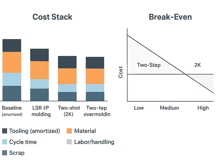
Two-step overmolding tends to have:
-
Lower upfront tooling cost
-
Higher variable cost (handling, alignment, WIP control)
-
Higher yield sensitivity (contamination/misalignment between steps)
Two-shot (2K) overmolding tends to have:
-
Higher tooling and qualification cost
-
Lower variable cost at scale (less handling, fewer transfers)
-
More stable alignment once the process is dialed in
Break-even volume depends on part geometry, required validation, automation level, and expected yield. A practical approach is to request two quotes—two-step and 2K—with stated assumptions (cavitation, cycle time basis, scrap allowance, inspection plan) and then run sensitivity cases for yield and labor.
Pitfalls and practical tips
Most cost and schedule overruns come from preventable mismatches: picking a process that can’t hold the interface, under-specifying CTQs, or discovering flash/adhesion issues after tooling is committed.
Common mistakes to avoid
-
Treating process selection as “material selection”: LSR vs plastic is not only about durometer or stiffness. It’s also about tooling strategy, inspection burden, and validation.
-
Leaving adhesion as a late-stage question (overmolding): if the interface is mission-critical, you need a defined attachment strategy (adhesion vs interlock) in the design stage.
-
Underestimating flash risk for LSR: flash control is not a trimming plan; it’s a mold design and maintenance plan.
-
Skipping environmental conditioning in validation: bonds and elastomers can pass initial tests and fail after aging, cycling, or chemical exposure.
Design-for-manufacturing priorities
DFM priorities that typically reduce both cost and risk:
-
Identify CTQs early and tie them to inspection methods (gage choice, sampling, visual standards).
-
For plastics: control wall transitions, design ribs thoughtfully, and avoid cosmetic weld lines on customer-facing surfaces.
-
For LSR: align parting line intent with functional surfaces; add venting features and specify flash limits that are inspectable.
-
For overmolding: design interlocks where practical, and control interface geometry so it’s tolerant to substrate variation.
⚠️ Warning: If your sealing function depends on a sharp edge or thin lip, validate how it demolds and how it behaves after conditioning. “Meets print at room temperature” can be a misleading success criterion.
Supplier selection cues
When comparing suppliers, look for evidence that they manage process capability, not just part delivery:
-
Can they explain how they will control the dominant defect modes (flash, warpage, voids, adhesion failures)?
-
Do they have a clear approach to validation (FAI/PPAP-style thinking, test fixtures, conditioning plans) appropriate to your risk level?
-
Are tooling ownership, maintenance cadence, and change control clearly documented?
-
For regulated programs: can they provide traceability and quality records aligned to your requirements (not generic promises)?
Conclusion
Plastic injection molding, LSR injection molding, and overmolding are all capable processes—but they optimize different outcomes.
-
Choose plastic injection molding when structure, throughput, and cost-at-volume are dominant, and cosmetic/warp risks can be engineered through gating and cooling.
-
Choose LSR injection molding when elastic function, sealing performance, and cleanliness/traceability controls drive the requirement—and when tooling is designed for venting and flash control.
-
Choose overmolding when integration removes real assembly risk or cost, and when the interface strategy (adhesion and/or mechanical interlocks) can be validated under real environmental conditions.
Next steps: collect the data that actually determines the answer—material requirements (chemical/temperature exposure), CTQs and cosmetic standards, annual volume and ramp profile, target inspection/validation plan, and any cleanroom/traceability needs—then engage short-listed suppliers for a DFM + tooling concept review before you lock the design.